تاريخ الفيزياء
علماء الفيزياء


الفيزياء الكلاسيكية
الميكانيك
الديناميكا الحرارية
الكهربائية والمغناطيسية
الكهربائية
المغناطيسية
الكهرومغناطيسية
علم البصريات
تاريخ علم البصريات
الضوء
مواضيع عامة في علم البصريات
الصوت
الفيزياء الحديثة
النظرية النسبية
النظرية النسبية الخاصة
النظرية النسبية العامة
مواضيع عامة في النظرية النسبية
ميكانيكا الكم
الفيزياء الذرية
الفيزياء الجزيئية
الفيزياء النووية
مواضيع عامة في الفيزياء النووية
النشاط الاشعاعي
فيزياء الحالة الصلبة
الموصلات
أشباه الموصلات
العوازل
مواضيع عامة في الفيزياء الصلبة
فيزياء الجوامد
الليزر
أنواع الليزر
بعض تطبيقات الليزر
مواضيع عامة في الليزر
علم الفلك
تاريخ وعلماء علم الفلك
الثقوب السوداء
المجموعة الشمسية
الشمس
كوكب عطارد
كوكب الزهرة
كوكب الأرض
كوكب المريخ
كوكب المشتري
كوكب زحل
كوكب أورانوس
كوكب نبتون
كوكب بلوتو
القمر
كواكب ومواضيع اخرى
مواضيع عامة في علم الفلك
النجوم
البلازما
الألكترونيات
خواص المادة
الطاقة البديلة
الطاقة الشمسية
مواضيع عامة في الطاقة البديلة
المد والجزر
فيزياء الجسيمات
الفيزياء والعلوم الأخرى
الفيزياء الكيميائية
الفيزياء الرياضية
الفيزياء الحيوية
الفيزياء والفلسفة
الفيزياء العامة
مواضيع عامة في الفيزياء
تجارب فيزيائية
مصطلحات وتعاريف فيزيائية
وحدات القياس الفيزيائية
طرائف الفيزياء
مواضيع اخرى

Amplitude limiting
 المؤلف:
Stan Gibilisco
المؤلف:
Stan Gibilisco
 المصدر:
Teach Yourself Electricity and Electronics
المصدر:
Teach Yourself Electricity and Electronics
 الجزء والصفحة:
375
الجزء والصفحة:
375
 6-5-2021
 3465
3465


+
-
20
Amplitude limiting
The forward breakover voltage of a germanium diode is about 0.3 V; for a silicon diode it is about 0.6 V. In the last chapter, you learned that a diode will not conduct until the forward bias voltage is at least as great as the forward breakover voltage. The “flip side” is that the diode will always conduct when the forward bias exceeds the breakover value. In this case, the voltage across the diode will be constant: 0.3 V for germanium and 0.6 V for silicon.
This property can be used to advantage when it is necessary to limit the amplitude of a signal, as shown in Fig. 1. By connecting two identical diodes back-to-back in parallel with the signal path (A), the maximum peak amplitude is limited, or clipped, to the forward breakover voltage of the diodes. The input and output waveforms of a clipped signal are illustrated at B. This scheme is sometimes used in radio receivers to prevent “blasting” when a strong signal comes in.
The downside of the diode limiter circuit is that it introduces distortion when limiting is taking place. This might not be a problem for reception of Morse code, or for signals that rarely reach the limiting voltage. But for voice signals with amplitude peaks that rise well past the limiting voltage, it can seriously degrade the audio quality, perhaps even rendering the words indecipherable.
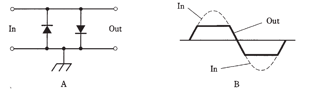
Fig. 1: At A, two diodes can work as a limiter. At B, the peaks are cut off by the action of the diodes.
 الاكثر قراءة في الألكترونيات
 اخر الاخبار
اخبار العتبة العباسية المقدسة

الآخبار الصحية


مواضيع ذات صلة
 قسم الشؤون الفكرية يصدر كتاباً يوثق تاريخ السدانة في العتبة العباسية المقدسة
 "المهمة".. إصدار قصصي يوثّق القصص الفائزة في مسابقة فتوى الدفاع المقدسة للقصة القصيرة
 (نوافذ).. إصدار أدبي يوثق القصص الفائزة في مسابقة الإمام العسكري (عليه السلام)