تاريخ الفيزياء
علماء الفيزياء


الفيزياء الكلاسيكية
الميكانيك
الديناميكا الحرارية
الكهربائية والمغناطيسية
الكهربائية
المغناطيسية
الكهرومغناطيسية
علم البصريات
تاريخ علم البصريات
الضوء
مواضيع عامة في علم البصريات
الصوت
الفيزياء الحديثة
النظرية النسبية
النظرية النسبية الخاصة
النظرية النسبية العامة
مواضيع عامة في النظرية النسبية
ميكانيكا الكم
الفيزياء الذرية
الفيزياء الجزيئية
الفيزياء النووية
مواضيع عامة في الفيزياء النووية
النشاط الاشعاعي
فيزياء الحالة الصلبة
الموصلات
أشباه الموصلات
العوازل
مواضيع عامة في الفيزياء الصلبة
فيزياء الجوامد
الليزر
أنواع الليزر
بعض تطبيقات الليزر
مواضيع عامة في الليزر
علم الفلك
تاريخ وعلماء علم الفلك
الثقوب السوداء
المجموعة الشمسية
الشمس
كوكب عطارد
كوكب الزهرة
كوكب الأرض
كوكب المريخ
كوكب المشتري
كوكب زحل
كوكب أورانوس
كوكب نبتون
كوكب بلوتو
القمر
كواكب ومواضيع اخرى
مواضيع عامة في علم الفلك
النجوم
البلازما
الألكترونيات
خواص المادة
الطاقة البديلة
الطاقة الشمسية
مواضيع عامة في الطاقة البديلة
المد والجزر
فيزياء الجسيمات
الفيزياء والعلوم الأخرى
الفيزياء الكيميائية
الفيزياء الرياضية
الفيزياء الحيوية
الفيزياء والفلسفة
الفيزياء العامة
مواضيع عامة في الفيزياء
تجارب فيزيائية
مصطلحات وتعاريف فيزيائية
وحدات القياس الفيزيائية
طرائف الفيزياء
مواضيع اخرى

Optical telescopes
 المؤلف:
A. Roy, D. Clarke
المؤلف:
A. Roy, D. Clarke
 المصدر:
Astronomy - Principles and Practice 4th ed
المصدر:
Astronomy - Principles and Practice 4th ed
 الجزء والصفحة:
p 374
الجزء والصفحة:
p 374
 1-9-2020
 2352
2352


+
-
20
Optical telescopes
In order to be able to point any telescope to particular directions in the sky, it is necessary to mount the collector on a ‘platform’ which can be rotated about two axes. In the case of a refractor, the objective is normally held in a tube which is then attached to the platform. For a large reflector, the optics are usually supported in an open tubular frame in order to reduce the overall weight. The open frame, however, is more susceptible to air currents which give deterioration in the telescope’s optical performance. Baffles may be included in the open frame system to cut out any extraneous sky light. It is very important that the tube or frame is free from flexure while the platform is oriented over its range of positions.
The simplest of mounting designs provides motion about vertical and horizontal axes and this is known as alt-azimuth mounting. Rotation about the vertical axis allows a telescope to be set in azimuth and rotation about the horizontal axis allows the telescope to be set in altitude. A simplified version of an alt-azimuth mounting is depicted in figure 1.
This system is not very convenient for astronomical purposes as the telescope needs to be driven simultaneously about both axes if an object is to be tracked during the course of a night: the drive rates constantly change through the night and also depend upon the position of the object on the celestial sphere.
By altering the orientation of the head containing the bearings for the two axes, so that one of the axes is set parallel to the direction of the Earth’s rotational pole, a more convenient form of mounting is obtained. This system is known as an equatorial mounting and its basic features are illustrated in figure 2. The axis which is parallel to the direction of the Earth’s pole is known as the polar axis and the axis at right angles to this is called the declination axis. In directing the telescope to any particular point on the sky, the required angular rotations about the axes are directly related to the equatorial coordinates of that point.
Consideration of the design of the equatorial mounting shows that the polar axis points in the direction given by ±90◦ declination. Rotation about the polar axis scans out a circle of constant declination on the celestial sphere whereas rotation about the declination axis scans out a circle of constant RA. It is standard practice to fit setting circles with encoders to the axes and, for larger telescopes, the settings are also displayed on a console. By using the setting circles, perhaps by control from the console, a particular point on the celestial sphere can be observed by setting the telescope to the correct hour angle—knowing the required RA and the local sidereal time—and to the correct declination. A preliminary setting can sometimes be achieved by fast slewing motors and final adjustment is then made by guidance motors. The slewing motors allow the telescope to be moved from object to object with the greatest possible speed.
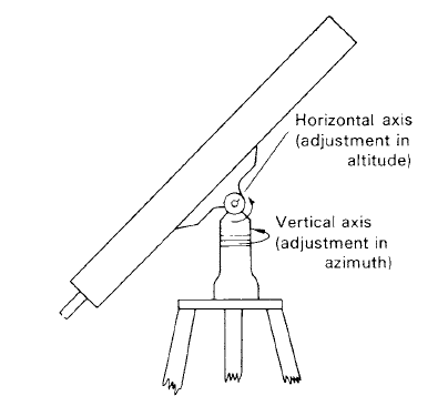
Figure 1. A simple alt-azimuth mounting.
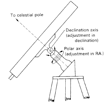
Figure 2. A simple equatorial mounting.
Once an equatorially-mounted telescope has been directed to a particular point on the celestial sphere, the point can be tracked or followed by applying rotation to the polar axis at an equal rate but in the opposite sense to the rotational speed of the Earth. Any errors in the following, such as those caused by flexure of the telescope or effects of atmospheric refraction, are compensated by the observer using supplementary guidance motors which are controlled by push-button. In some elaborate systems, exact following is achieved by image-position-sensing devices providing a servo-system with error signals which are made to control the guidance motors automatically.
The drive to a telescope is usually applied by an electric synchronous motor, via a gear train, to a worm and large wheel. A simple look at the accuracy required of a drive shows that, in general, some electronic elaboration is required.
Suppose that for an observation, it is hoped that the following of an image will match the resolution of the telescope. For a good telescope, the resolution may be of the order of 0·1 seconds of arc and this is equivalent to a movement of the sky during a period given by 0·1/15 seconds of time. If the observation takes 1 hr to make, the following must be good to
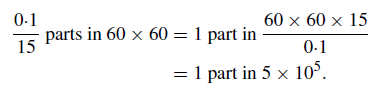
A synchronous motor driven directly from the mains frequency will normally be insufficient to provide such a high accuracy of following, as the variation in the mains frequency is usually greater than this.
There are several different methods which are used for controlling the speed of rotation of the telescope drive worm shaft. Perhaps the most common is the servo-system method whereby the speed of the following motor is constantly referred to a standard stabilized frequency generated by a quartz crystal. The guidance motors are usually connected to the worm shaft by means of mechanical differentials. Figure 3 shows the basic elements of a telescope drive and guidance system.
In some systems, the guidance motors can be dispensed with if, by the push-button control, the reference frequency can be instantaneously re-set to a value which is either greater or smaller than that used for following, depending on the sense of the adjustment required. In another system, the stabilized frequency, after appropriate division, can be made to drive a stepping motor directly. By using the push-button control to alter the dividing factor, the following rate can be altered and, hence, guidance can be achieved in this way.
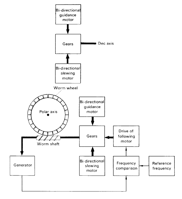
Figure 3. A telescope drive and guidance system.
 الاكثر قراءة في مواضيع عامة في علم الفلك
 اخر الاخبار
اخبار العتبة العباسية المقدسة

الآخبار الصحية


مواضيع ذات صلة
 قسم الشؤون الفكرية يصدر كتاباً يوثق تاريخ السدانة في العتبة العباسية المقدسة
 "المهمة".. إصدار قصصي يوثّق القصص الفائزة في مسابقة فتوى الدفاع المقدسة للقصة القصيرة
 (نوافذ).. إصدار أدبي يوثق القصص الفائزة في مسابقة الإمام العسكري (عليه السلام)