تاريخ الفيزياء
علماء الفيزياء


الفيزياء الكلاسيكية
الميكانيك
الديناميكا الحرارية
الكهربائية والمغناطيسية
الكهربائية
المغناطيسية
الكهرومغناطيسية
علم البصريات
تاريخ علم البصريات
الضوء
مواضيع عامة في علم البصريات
الصوت
الفيزياء الحديثة
النظرية النسبية
النظرية النسبية الخاصة
النظرية النسبية العامة
مواضيع عامة في النظرية النسبية
ميكانيكا الكم
الفيزياء الذرية
الفيزياء الجزيئية
الفيزياء النووية
مواضيع عامة في الفيزياء النووية
النشاط الاشعاعي
فيزياء الحالة الصلبة
الموصلات
أشباه الموصلات
العوازل
مواضيع عامة في الفيزياء الصلبة
فيزياء الجوامد
الليزر
أنواع الليزر
بعض تطبيقات الليزر
مواضيع عامة في الليزر
علم الفلك
تاريخ وعلماء علم الفلك
الثقوب السوداء
المجموعة الشمسية
الشمس
كوكب عطارد
كوكب الزهرة
كوكب الأرض
كوكب المريخ
كوكب المشتري
كوكب زحل
كوكب أورانوس
كوكب نبتون
كوكب بلوتو
القمر
كواكب ومواضيع اخرى
مواضيع عامة في علم الفلك
النجوم
البلازما
الألكترونيات
خواص المادة
الطاقة البديلة
الطاقة الشمسية
مواضيع عامة في الطاقة البديلة
المد والجزر
فيزياء الجسيمات
الفيزياء والعلوم الأخرى
الفيزياء الكيميائية
الفيزياء الرياضية
الفيزياء الحيوية
الفيزياء والفلسفة
الفيزياء العامة
مواضيع عامة في الفيزياء
تجارب فيزيائية
مصطلحات وتعاريف فيزيائية
وحدات القياس الفيزيائية
طرائف الفيزياء
مواضيع اخرى

Inductors
 المؤلف:
Richard Fitzpatrick
المؤلف:
Richard Fitzpatrick
 المصدر:
Classical Electromagnetism
المصدر:
Classical Electromagnetism
 الجزء والصفحة:
p 186
الجزء والصفحة:
p 186
 9-1-2017
 3418
3418


+
-
20
Inductors
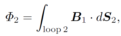
We have now completed our investigation of electrostatics. We should now move on to magnetostatics i.e., the study of steady magnetic fields generated by steady currents. Let us skip this topic. It contains nothing new (it merely consists of the application of Ampere's law and the Biot-Savart law) and is also exceptionally dull! We have learned about resistance and capacitance. Let us now investigate inductance. Electrical engineers like to reduce all pieces of electrical apparatus to an equivalent circuit consisting only of e.m.f. sources (e.g., batteries), inductors, capacitors, and resistors. Clearly, once we understand inductors we shall be ready to apply the laws of electromagnetism to real life situations. Consider two stationary loops of wire, labeled 1 and 2. Let us run a steady current I1 around the first loop to produce a field B1. Some of the field lines of B1 will pass through the second loop. Let ɸ2 be the flux of B1 through loop 2:
 (1.1)
(1.1)
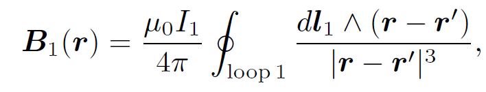
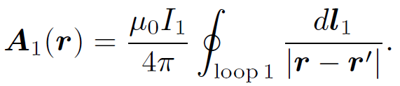
where dS2 is a surface element of loop 2. This flux is generally quite difficult to calculate exactly (unless the two loops have a particularly simple geometry). However, we can infer from the Biot-Savart law,
 (1.2)
(1.2)
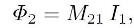
that the magnitude of B1 is proportional to the current I1. This is ultimately a consequence of the linearity of Maxwell's equations. Here, dl1 is a line element of loop 1 located at position vector rʹ. It follows that the flux ɸ2 must also be proportional to I1. Thus, we can write
 (1.3)
(1.3)
where M21 is the constant of proportionality. This constant is called the mutual inductance of the two loops. Let us write the field B1 in terms of a vector potential A1, so that
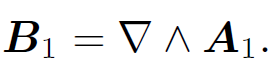 (1.4)
(1.4)
It follows from Stokes' theorem that
 (1.5)
(1.5)
where dl2 is a line element of loop 2. However, we know that
 (1.6)
(1.6)
The above equation is just a special case of the more general law,
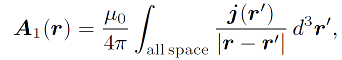 (1.7)
(1.7)
for j(rʹ) = dl1I1=dl1dA and d3rʹ = dl1dA, where dA is the cross sectional area of loop 1. Thus,
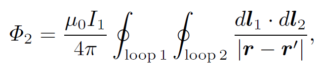 (1.8)
(1.8)
where r is now the position vector of the line element dl2 of loop 2. The above equation implies that
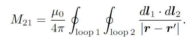 (1.9)
(1.9)
In fact, mutual inductances are rarely worked out from first principles it is usually too difficult. However, the above formula tells us two important things. Firstly, the mutual inductance of two loops is a purely geometric quantity, having to do with the sizes, shapes, and relative orientations of the loops. Secondly, the integral is unchanged of we switch the roles of loops 1 and 2. In other words,
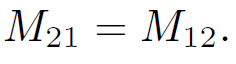 (1.10)
In fact, we can drop the subscripts and just call these quantities M. This is a rather surprising result. It implies that no matter what the shapes and relative positions of the two loops, the flux through loop 2 when we run a current I around loop 1 is exactly the same as the flux through loop 1 when we send the same current around loop 2. We have seen that a current I flowing around some loop, 1, generates a magnetic flux linking some other loop, 2. However, flux is also generated through the first loop. As before, the magnetic field, and, therefore, the flux ɸ, is proportional to the current, so we can write
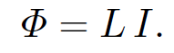 (1.11)
The constant of proportionality L is called the self inductance. Like M it only depends on the geometry of the loop. Inductance is measured in S.I. units called henries (H); 1 henry is 1 volt-second per ampere. The henry, like the farad, is a rather unwieldy unit since most real life inductors have a inductances of order a micro-henry. Consider a long solenoid of length l and radius r which has N turns per unit length, and carries a current I. The longitudinal (i.e., directed along the axis of the solenoid) magnetic field within the solenoid is approximately uniform, and is given by
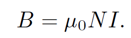 (1.12)
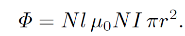
This result is easily obtained by integrating Ampere's law over a rectangular loop whose long sides run parallel to the axis of the solenoid, one inside the solenoid and the other outside, and whose short sides run perpendicular to the axis. The magnetic flux though each turn of the loop is B πr2 = μ0NI πr2. The total flux through the solenoid wire, which has Nl turns, is
 (1.13)
Thus, the self inductance of the solenoid is
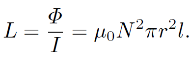 (1.14)
Note that the self inductance only depends on geometric quantities such as the number of turns in the solenoid and the area of the coils. Suppose that the current I flowing through the solenoid changes. We have to assume that the change is sufficiently slow that we can neglect the displacement current and retardation effects in our calculations. This implies that the typical time-scale of the change must be much longer than the time for a light ray to traverse the circuit. If this is the case then the above formulae remain valid. A change in the current implies a change in the magnetic flux linking the solenoid wire, since ɸ = LI. According to Faraday's law, this change generates an e.m.f. in the coils. By Lenz's law, the e.m.f. is such as to oppose the change in the current i.e., it is a back e.m.f. We can write
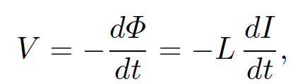 (1.15)
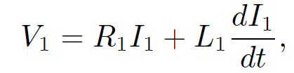
where V is the generated e.m.f. Suppose that our solenoid has an electrical resistance R. Let us connect the ends of the solenoid across the terminals of a battery of e.m.f. V. What is going to happen? The equivalent circuit is shown below. The inductance and resistance of the solenoid are represented by a perfect inductor L and a perfect resistor R connected in series. The voltage drop across the inductor and resistor is equal to the e.m.f. of the battery, V. The voltage drop across the resistor is simply
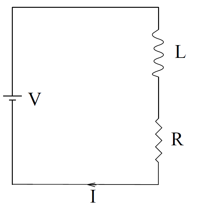
IR, whereas the voltage drop across the inductor (i.e., minus the back e.m.f.) is LdI/dt. Here, I is the current flowing through the solenoid. It follows that
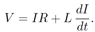 (1.16)
This is a differential equation for the current I. We can rearrange it to give
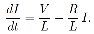 (1.17)
The general solution is
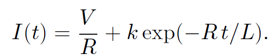 (1.18)
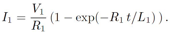
The constant k is fixed by the boundary conditions. Suppose that the battery is connected at time t = 0, when I = 0. It follows that k = -V/R, so that
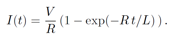 (1.19)
It can be seen from the diagram that after the battery is connected the current ramps up and attains its steady state value V/R (which comes from Ohm's law) on the characteristic time-scale
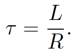 (1.20)
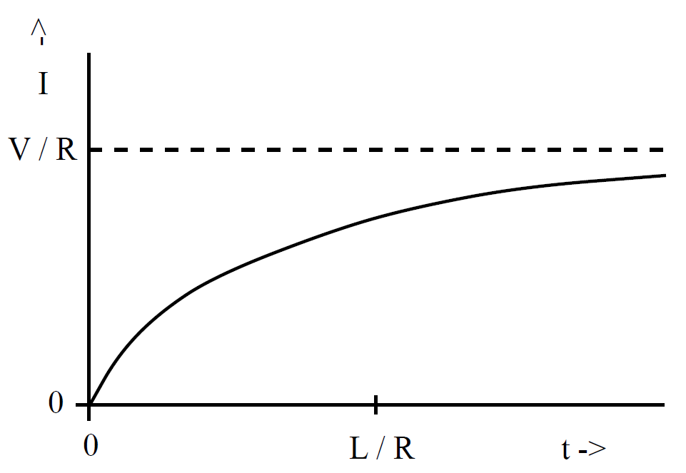
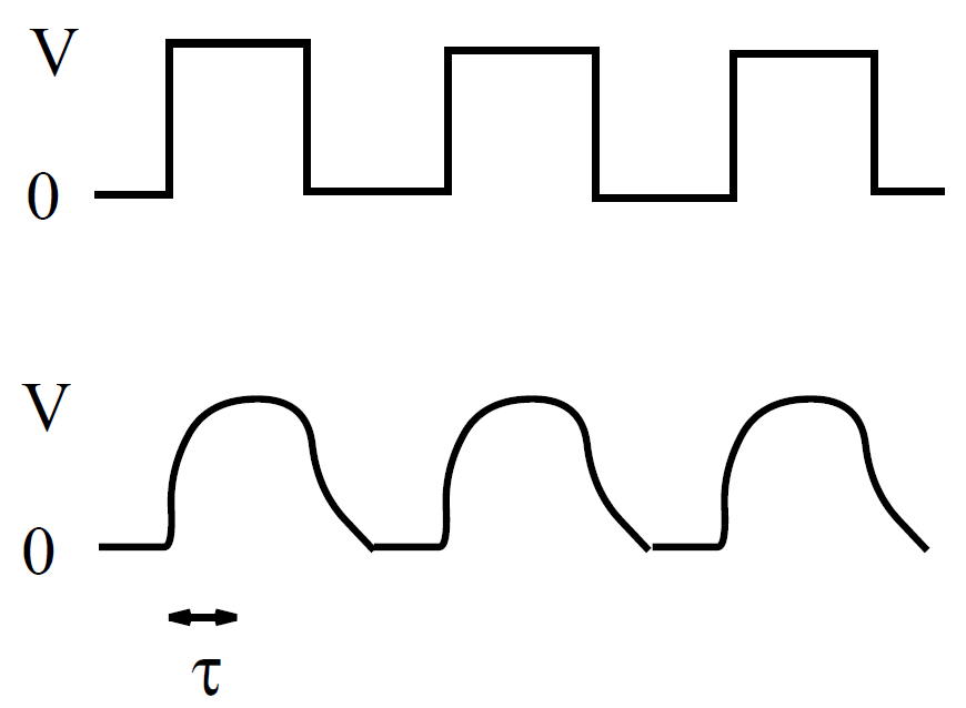
This time-scale is sometimes called the ''time constant" of the circuit, or, some- what unimaginatively, the ''L/R time" of the circuit. We can now appreciate the significance of self-inductance. The back e.m.f. generated in an inductor, as the current tries to change, effectively prevents the current from rising (or falling) much faster than the L/R time. This effect is sometimes advantageous, but often it is a great nuisance. All circuit elements possess some self-inductance, as well as some resistance, so all have a finite L/R time. This means that when we power up a circuit the current does not jump up instantaneously to its steady state value. Instead, the rise is spread out over the L/R time of the circuit. This is a good thing. If the current were to rise instantaneously then extremely large electric fields would be generated by the sudden jump in the magnetic field, leading, inevitably, to breakdown and electric arcing. So, if there were no such thing as self-inductance then every time you switched an electric circuit on or off there would be a big blue flash due to arcing between conductors. Self-inductance can also be a bad thing. Suppose that we possess a fancy power supply, and we want to use it to send an electric signal down a wire (or transmission line). Of course, the wire or transmission line will possess both resistance and inductance, and will, therefore, have some characteristic L/R time. Suppose that we try to send a square wave signal down the line. Since the current in the line cannot rise or fall faster than the L/R time, the leading and trailing edges of the signal get smoothed out over an L/R time. The typical difference between the signal fed into the wire (upper trace) and that which comes out of the other end (lower trace) is illustrated in the diagram below. Clearly, there is little point having a fancy power supply unless you also possess a low inductance wire or transmission line, so that the signal from the power supply can be transmitted to some load device without serious distortion.
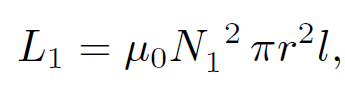
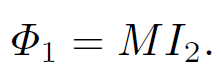
Consider, now, two long thin solenoids, one wound on top of the other. The length of each solenoid is l, and the common radius is r. Suppose that the bottom coil has N turns per unit length and carries a current I1. The magnetic flux passing through each turn of the top coil is μ0N1I1 πr2, and the total flux linking the top coil is therefore ɸ2 = N2l μ0N1I1 πr2, where N2 is the number of turns per unit length in the top coil. It follows that the mutual inductance of the two coils, defined ɸ2 = MI1, is given by
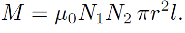 (1.21)
Recall that the self-inductance of the bottom coil is
 (1.22)
and that of the top coil is
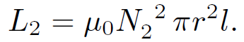 (1.23)
Hence, the mutual inductance can be written
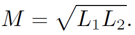 (1.24)
Note that this result depends on the assumption that all of the flux produced by one coil passes through the other coil. In reality, some of the flux ''leaks" out, so that the mutual inductance is somewhat less than that given in the above formula. We can write
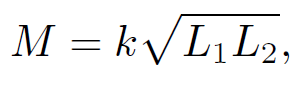 (1.25)
where the constant k is called the ''coefficient of coupling" and lies in the range 0 ≤ k ≤ 1. Suppose that the two coils have resistances R1 and R2. If the bottom coil has an instantaneous current I1 °owing through it and a total voltage drop V1, then the voltage drop due to its resistance is I1R. The voltage drop due to the back e.m.f. generated by the self-inductance of the coil is L1 dI1/dt. There is also a back e.m.f. due to the inductive coupling to the top coil. We know that the flux through the bottom coil due to the instantaneous current I2 flowing in the top coil is
 (1.26)
Thus, by Faraday's law and Lenz's law the back e.m.f. induced in the bottom coil
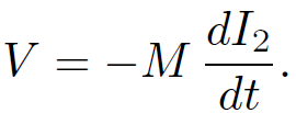 (1.27)
The voltage drop across the bottom coil due to its mutual inductance with the top coil is minus this expression. Thus, the circuit equation for the bottom coil is
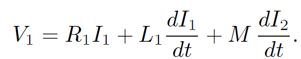 (1.28)
Likewise, the circuit equation for the top coil is
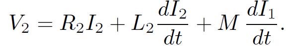 (1.29)
Here, V2 is the total voltage drop across the top coil. Suppose that we suddenly connect a battery of e.m.f. V1 to the bottom coil at time t = 0. The top coil is assumed to be open circuited, or connected to a voltmeter of very high internal resistance, so that I2 = 0. What is the e.m.f. generated in the top coil? Since I2 = 0, the circuit equation for the bottom coil is
 (1.30)
where V1 is constant, and I1(t = 0) = 0. We have already seen the solution to this equation:
 (1.31)
The circuit equation for the top coil is
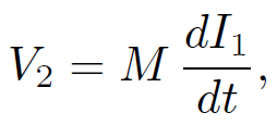 (1.32)
giving
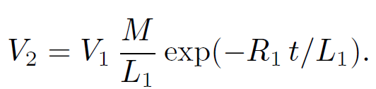 (1.33)
It follows from Eq. (1.24) that
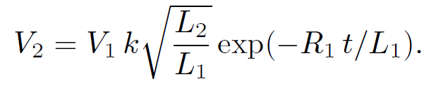 (1.34)
Since L1, 2  N12,2 we obtain
 (1.35)
Note that V2(t) is discontinuous at t = 0. This is not a problem since the resistance of the top circuit is infinite, so there is no discontinuity in the current (and, hence, in the magnetic field). But, what about the displacement current, which is proportional to ∂E/∂t? Surely, this is discontinuous at t = 0 (which is clearly unphysical)? The crucial point, here, is that we have specifically neglected the displacement current in all of our previous analysis, so it does not make much sense to start worrying about it now. If we had retained the displacement current in our calculations we would find that the voltage in the top circuit jumps up, at
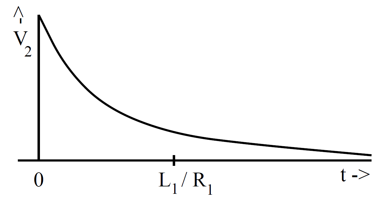
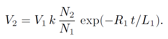
t = 0, on a time-scale similar to the light traverse time across the circuit (i.e., the jump is instantaneous to all intents and purposes, but the displacement current remains finite). Now,
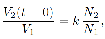 (1.36)
so if N2 >> N1 the voltage in the bottom circuit is considerably amplified in the top circuit. This effect is the basis for old-fashioned car ignition systems. A large voltage spike is induced in a secondary circuit (connected to a coil with very many turns) whenever the current in a primary circuit (connected to a coil with not so many turns) is either switched on or off. The primary circuit is connected to the car battery (whose e.m.f. is typically 12 volts). The switching is done by a set of points which are mechanically opened and closed as the engine turns. The large voltage spike induced in the secondary circuit as the points are either opened or closed causes a spark to jump across a gap in this circuit. This spark ignites a petrol/air mixture in one of the cylinders. You might think that the optimum configuration is to have only one turn in the primary circuit and lots of turns in the secondary circuit, so that the ratio N2/N1 is made as large as possible. However, this is not the case. Most of the magnetic field lines generated by a single turn primary coil are likely to miss the secondary coil altogether. This means that the coefficient of coupling k is small, which reduces the voltage induced in the secondary circuit. Thus, you need a reasonable number of turns in the primary coil in order to localize the induced magnetic field so that it links effectively with the secondary coil.
 الاكثر قراءة في الكهربائية
 اخر الاخبار
اخبار العتبة العباسية المقدسة

الآخبار الصحية


مواضيع ذات صلة
 قسم الشؤون الفكرية يصدر كتاباً يوثق تاريخ السدانة في العتبة العباسية المقدسة
 "المهمة".. إصدار قصصي يوثّق القصص الفائزة في مسابقة فتوى الدفاع المقدسة للقصة القصيرة
 (نوافذ).. إصدار أدبي يوثق القصص الفائزة في مسابقة الإمام العسكري (عليه السلام)