آخر المواضيع المضافة

 النبات
الحيوان
الأحياء المجهرية
علم الأمراض
التقانة الإحيائية
التقنية الحيوية المكروبية
التقنية الحياتية النانوية
علم الأجنة
الأحياء الجزيئي
علم وظائف الأعضاء
الغدد
المضادات الحيوية
النبات
الحيوان
الأحياء المجهرية
علم الأمراض
التقانة الإحيائية
التقنية الحيوية المكروبية
التقنية الحياتية النانوية
علم الأجنة
الأحياء الجزيئي
علم وظائف الأعضاء
الغدد
المضادات الحيوية| Atomic Force Microscopy |


|
|
Read More
Date: 9-5-2021
Date: 29-11-2015
Date: 1-3-2021
|
Atomic Force Microscopy
Binnig, Quate, and Gerber developed a scanning probe technique known as atomic force microscopy) AFM) and as scanning force microscopy. Unlike its predecessor, scanning tunneling microscope (STM), AFM also images nonconducting samples, such as biological specimens, in a liquid environment at molecular and even atomic resolution. Currently, structural information about biological materials at the molecular level is obtained from other microscopic techniques, including electron microscopy, electron crystallography, X-ray crystallography, nuclear magnetic resonance (NMR) spectroscopy, and vibrational spectroscopy. These techniques require extensive sample preparation and unfavorable operating environments, and they are unsuitable for providing real-time functional information. Molecular function is studied by various molecular biological, biochemical, and electrophysiological techniques, but it is difficult to combine both structural and functional studies in one technique. Moreover, these techniques provide incomplete information about the surfaces of biological macromolecules, the very sites of their interactions with other molecules. In contrast, AFM images the surfaces of biological specimens, where most of the regulatory biochemical and other signals are directed. Other microscopic techniques also image surfaces, for example, the scanning electron microscope (SEM), but AFM images living cells and molecules in a liquid environment at comparable and often greater resolution.
1. Principle of Operation
AFM is based on the general physical principle that the interactive force between two bodies is inversely proportional to some power of the distance separating them and on the physicochemical natures of the interacting bodies. A tip that is sharp on the molecular scale is attached to a cantilevered spring: As it is moved across the surface of the specimen, it is deflected by the interactive forces between the atoms of the tip and those of the specimen (see Fig. 1 of Scanning Probe Techniques). Because the spring constant of the commonly used cantilevers (10–1 to 10-2 N/m) is much smaller than the intermolecular vibrational spring constant of the atoms in the specimen (10 N/m), the cantilever senses exquisitely small forces exerted by the individual sample atoms. The tip's deflection is a measure of the forces sensed by the cantilever, which are transduced to generate molecular images.
In practice, a microfabricated cantilevered tip is pressed against a sample surface by a small tracking (loading) force. The tip is raster-scanned in the x-y plane over the specimen by moving the sample beneath the tip or by moving the tip over the sample. The sample's vertical position (z) is also monitored. The three planes of movement are controlled by a piezoelectric xyz scanner, and the information about the three coordinates is used to create the image (Fig. 1). The cantilevered tip is brought sufficiently close to touch the sample (known as “contact” mode), or it oscillates at a finite distance (>a few nanometers) from the surface (“noncontact” mode). A noncontact mode microscope has the advantage that it does not perturb the sample, but the lateral resolution in these microscopes is poor, and hence they are not commonly used for biological imaging.

Figure 1. Schematic illustration of the operating principle of multimodal atomic force microscopes. (a) Schematic of the combined scanning ion conductance and atomic force microscope. A pipette serves as the probe: A laser beam reflecting from a mirror glued to the back of the pipette provides the deflection signal for the topographic image as the pipette is moved across the surface. The electrode has a nanometer-sized hole. Electrodes within the pipette and in the bath measure electrical currents (R. A. Proksch, R. Lal, P. K. Hansma, G. Morse, and G. Stucky (1996) Biophys. J. 71, 2155–2157). (b) A combined light and atomic force microscope. The first focal point is located inside the upper portion of the piezoelectric scanner. After the positions of the lenses are adjusted, the scanning focused spot accurately tracks the cantilever, and the zero-deflection signal from the four-segment photodiode is independent of the position within the scan area. One of the key advantages of this new AFM is that there is optical access to the sample from above and below. Thus, the new AFM can be combined with an optical microscope of high numerical aperture. The other key advantage is that the sample is stationary during scanning and can be large, so that techniques for on-line perturbations and recordings are easily incorporated. For details, see P. K. Hansma, B. Drake, D. Grigg, C. B. Prater, F. Yasher, G. Gurley, V. Elings, S. Feinstein, and R. Lal (1994) J. Appl. Phys. 76, 796–799; R. Lal and S. A. John (1994) Am. J. Physiol. 256, C1–C21.
The deflective force is translated into a detectable signal in several ways. The most common is by an optical lever system (Fig. 1). A monochromatic laser beam reflects from the upper face of the cantilever, the angular direction of which changes as the cantilevered tip undergoes deflections. The reflected beams are captured and converted into electrical signals by position-sensitive multisegmented photodetectors. Such an optical lever amplifies the cantilever's deflection as much as a thousandfold, so deflections even less than a nanometer are measured.
1.1. Modes of Operation
Using an appropriate feedback system, the cantilever's deflection is kept constant or left to respond freely to the sensed forces. In the constant deflection mode (also called “constant force mode”), the feedback loop changes the height of the sample (to maintain the constant deflection) by adjusting the voltage applied to the z portion of the xyz piezoelectric scanner. The amount of z change corresponds to the sample's topological height at each point in the x-y raster. Combining the information from the three coordinates generates the 3-D image.
In the variable deflection mode (“constant height mode”), the feedback loop is open so that the cantilever deflection is proportional to the change in the tip–sample interaction, that is the force sensed by the cantilever. The surface image is constructed from the deflection information. It is called the constant height mode because the z component of the piezoelectric scanner does not change appreciably. This is usually unsuitable for a sample with large surface corrugation (e.g., cells), because the force fluctuations, and thus the cantilever's deflections, are enormous and often result in disengagement of the tip from the sample.
“Error mode” imaging relies on the imperfection in the feedback loop to operate in the constant-deflection mode. The error signal is amplified to yield contour information in the z plane. In the error mode, the feedback loop gathers high-frequency information that is normally not acquired in the constant deflection mode. This high-frequency information provides details of sharp contour changes (edges) in the sample. Measurements of actual height in error mode imaging are not accurate, however, in contrast to the other modes of operation. The main advantage of error mode operation is that imaging occurs without exerting high forces on the sample.
In “tapping mode” imaging, the cantilever is oscillated at very high frequency, normally near its resonance frequency, as it scans the sample. As the tip approaches the sample surface, its oscillatory amplitude decreases because of energy loss when the tip “taps” the surface. The amplitude of the cantilever oscillation is detected and used by the feedback system to adjust the tip–sample distance for constant amplitude. This ensures a much shorter tip–sample contact time, and smaller lateral forces are exerted on the cantilever. In this way, this mode has been successfully used for imaging delicate and individual macromolecules. The disadvantage of this mode of operation is that the vertical imaging force can be large, thus increasing the possibility of sample damage.
1.2. Sample Preparation
AFM is used to image specimens in aqueous, semiaqueous, or dry conditions. The imaging condition is normally chosen to maintain the specimen in as near a lifelike condition as possible. Where resolution takes priority over the physiological condition, however, the investigator is not as constrained. Imaging conditions also influence the choice of substrate, the stability of the specimen with respect to the tip interaction, and the preservation of the specimen with respect to its physiological or biochemical functions. At present, investigators rely on an empirical approach to find a suitable method, and probably will for some time to come. When it “works”, the search stops for the “ideal support” or buffer.
The physicochemical characteristics of the sample determine or suggest ways under which it can be imaged. Problems encountered are as simple as getting the sample to attach to the support. Techniques for sample support include drying down of samples and adsorption to specially prepared surfaces. For example, imaging of plasmid DNA is vastly improved in to both resolution and consistency, under propanol, which increases the humidity and produces a more hydrated condition. This allows reducing the tip-tracking force exerted on the sample to <1 nN , thus decreasing sample deformation.
The interaction of the sample with the support determines the magnitude of the imaging force. If the sample does not adhere tightly to the support, low tracking forces must be used for imaging, or the tip literally sweeps the sample from the support. Originally, graphite (hydrophobic and uncharged,( mica (hydrophilic and negatively charged), and glass (usually negatively-charged) were the supports most routinely used. These supports can also be modified chemically to adjust their hydropathy, charge density, and polarity. Today the repertoire has expanded greatly, and examples include gold treated with a variety of agents for DNA imaging. Gold supports maintained under potential (voltage) control have been used for DNA imaging with the scanning transmission microscope, and they may also prove useful for AFM.
The specimen support can also be modified or coated chemically so that it acts as a ligand for the sample and thus orients the specimen in a defined way. It is also possible to use artificial systems to generate constraints where there were none before. Examples include imaging isolated cholera toxin molecules incorporated into synthetic phospholipid bilayers, followed by covalent cross-linking or imaging the vaccinia virus protrusion out of living cells held by a suction pipette.
1.3. Forces in AFM
Interactive forces that deflect the cantilevered-tip are attractive or repulsive, and they vary depending on the mode of operation and the conditions used for imaging.
In contact mode imaging, the tip is deflected mainly by the repulsive forces from the overlapping electron orbitals of the atoms of the tip and sample. The dominant attractive force is a van der Waals interaction due primarily to the nonlocalized dipole–dipole interactions among atoms of the tip and specimen. When imaging in air, (attractive) surface tension is also present because of adsorbed water layers. For imaging in fluids, electrostatic interactions between charges on the specimen and the tip )occurring either naturally or induced by to polarization), osmotic pressure due to charge movements and rearrangements, and structural forces due to hydration, solvation, or adhesion enable a reduction in the net imaging force although both the meniscus and surface tension forces are abolished.
The interplay of local forces determines the stability of the specimen and the resolution. Theoretically the force should be ≤10–10 N for nonperturbed biological imaging. The sensitivity of AFM is sufficient to record small interactive forces, including the breaking of hydrogen bonds. Imaging in contact mode under liquid, but with a net attractive rather than repulsive force, increases the resolution significantly and has produced true atomic resolution, even with an imaging force of 10-11 N. As explained below, however, successful imaging of cells, membranes, and isolated proteins has been obtained with forces as large as 10–7 N.
In principle, any movement of the tip caused by its interaction with the sample in the x, y, or z directions provides information about the specimen's topography. To date, most information has been obtained from z deflections. Improvements in hardware and software have, however, allowed recording movements in the zy or zx planes and measurement of lateral forces for image generation. The contribution of lateral forces to image contrast generation can be substantial.
1.4. Resolution in AFM
1.4.1. Spatial Resolution
The limit of spatial resolution for AFM is not well defined because, unlike conventional microscopies, the images are formed by reconstructing the contours of interacting forces between the specimen and tip. The operating resolution in AFM is defined as the minimum size of two adjacent features that can be distinguished clearly. By selecting a small scan size and suitable operating conditions, one can distinguish two structures that are less than a nanometer apart. Image processing tools used to define resolution in X-ray crystallography and electron microscopy studies may not give correct results for AFM. The operating resolution can be divided into three categories:
1. Instrumental resolution: The lateral resolution is about 1 Å and is determined by the limitations of the hardware. The vertical resolution is 0.1 Å, and hence molecular perturbations on a sample surface can be imaged.
2. Target resolution: The lateral resolution achieved depends on the characteristics of the tip, the operating environment, and the nature of the specimen. For crystalline solid specimens and many inorganic materials, atomic resolution of 1 to 2 Å has been achieved.
3. Resolution in biological specimens: The nature of the biological samples and their preparation play a key role in determining the resolution limits. For the surface of a living cell, the resolution is relatively poor (~10 nm) but greater than that by light microscopy and comparable to that by scanning electron microscopy. In a biological specimen whose the density of particles is high and mobility is limited (e.g., proteins in a membrane), the resolution is comparable to that of a crystalline specimen.
1.4.2. Temporal Resolution
Temporal resolution is limited by the maximum speed at which a specimen can be scanned and still have the tip accurately track surface features. Preliminary studies suggest that the scan speed should be ≤2.2 µm/s for 1 nm spatial resolution on soft and deformable biological materials imaged in aqueous solution. Thus, membrane macromolecules whose dimensions are 10 nm × 10 nm (such as channels and receptors) divided into 10 × 10 pixels (with pixel size ~1 nm) require about 45 to 50 ms to image. However, if only a single line is scanned, the image can be repeated every 4 to 5 ms. Measuring at a single point, rather than scanning, increases the temporal resolution significantly, and hence it is possible to obtain spatial information at very short time intervals. The temporal resolution also depends on the mode of operation (constant deflection or constant height mode), operating environment (solvents, pH, viscosity, elasticity), and the nature of the interactions between tip and sample. In the constant-height mode, the scan speed is limited by the speed with which the deflection of the cantilever changes in reacting to surface features. In the constant deflection mode, the scan speed is limited by how the speed with which the piezo scanner changes its z component. There is ultimately a limit to the temporal resolution imposed by the low-pass filter used to eliminate sampling noise. These filters typically have a cutoff frequency of ~15 kHz , corresponding to a time resolution of 67 µs.
Temporal resolution also depends on the material being imaged. Individual molecules at molecular resolution require faster scan speeds than cells at lower resolution. Molecular movements of biological macromolecules can be correlated with their lateral diffusion constant. Lipids in a bilayer have a typical diffusion constant of 10–8 cm2/s , corresponding to a mean velocity of ~2 µm/s. The proteins embedded in natural biomembranes have diffusion constants many orders of magnitude lower (e.g., the acetylcholine receptor in myoblast patches has a diffusion constant <3.0 × 10⁻¹² cm2/s. Thus it is quite possible to obtain images at molecular resolution of proteins and other macromolecules that are properly anchored in a lipid bilayer or immobilized on a substrate.
1.5. Identity of Imaged Structure
Although AFM provides molecular-resolution surface information for crystalline and amorphous materials, it is often difficult to define the nature of individual components, especially if the specimen contains a heterogeneous population of structures. This is the case with most biological systems, except in favorable systems like membranes that contain a crystalline patch of similar protein molecules. For mixed macromolecules, it is essential to compare the information obtained from AFM with that from alternative or complementary techniques, such as structural probes of electron microscopy and X-ray crystallography, biochemical and immunological binding assays, pharmacological labeling, and electrophysiological measurements.
1.6. Examples of AFM Imaging
1.6.1. Cells and Cellular Processes
AFM images cellular and subcellular structures in physiological conditions at a resolution far exceeding that of optical microscopes. Living cells have been imaged in aqueous conditions with a resolution as small as 10 nm. By applying a larger imaging force, intracellular organelles and cytoskeleton networks have also been examined (Fig. 2). The ability to view structures beneath the plasma membrane is puzzling. Two possible mechanisms are (1) the tip penetrates the bilayer and images the substructure or (2) the plasma membrane drapes around the cytoskeletal fibers and the tip images the contour of the plasma membrane. If the “drape” model is correct, these observations give wonderful demonstrations of the flexibility of biological membranes and a potential tool for measuring the “drape characteristics” of natural and synthetic membranes.

Figure 2. Images obtained with AFM. (a) Error-mode AFM image of a fixed atrial cell. The cytoskeletal network and cell nucleus are visible. [S. Shroff, D. Saner, and R. Lal (1995) Am. J. Physiol. 269, C286–292.] (b) AFM error mode image a freeze-fracture replica of atrial tissue. Details can be identified in the mitochondrion and in the atrial granules and vesicles. Scale Bar: 1 mm. [L. Kordylewsky, D. Saner, and R. Lal (1994) J. Microsc. 173, 173–181.] (c) Error-mode AFM image of a neurite outgrowth in PC-12 cells treated with nerve growth factor and dibutyryl cyclic AMP. For details, see R. Lal, B. Drake, D. Blumberg, D. Saner, P. K. Hansma, S. Feinstein (1995) Am. J. Physiol. 269, C275–C285. (d) Lambd DNA under propanol using a regular silicon nitride tip. Note the sharp bends in the strands and a fairly regular series of lumps along the strands, 6 to 8 nm apart. The strand width is 7 to 9 nm, greater than expected, which may result from the relatively large size of the tip. Scan size is 1000 nm × 1000 nm (courtesy H. Hansma, H. G. Hansma, R. L. Sinsheimer, M Q. Li, and P. K. Hansma (1992) Nucleic Acids Res. 20, 3585–3590). (e) AFM height mode image of a single connexon (a gap junction hemichannel) imaged on its cytoplasmic face. The subunit structure, a central pore, and the spacing between connections are apparent [S. A. John, D. Saner, J. Pitts, M. Finbow, and R. Lal (1997) J. Struct. Biol. 120, 22–31).] (f( High-resolution AFM imaging of a single acetylcholine receptor expressed in Xenopus oocytes. The channel has a diameter of ~10.5 nm , and the five subunits (~1 to 1.5 nm in diameter) that have a central pore-like structure are shown. The protrusion of one unit is not apparent in the image [R. Lal (1998) Scanning Microsc. 10, 81–96].
In AFM imaging, the scan area can be varied from the micron to nanometer range, and hence it is possible to image features ranging from whole cells to individual macromolecules, such as ion channels and receptors (Fig. 2). In air-dried, hydrated Xenopus oocytes in which acetylcholine receptor proteins are expressed, the characteristic pentameric subunit structure of the expressed receptor has been observed after removing of the follicle layer. This technique of imaging expressed proteins on or in the surface of the plasma membrane of oocytes will shortly enable the characterization of a myriad of ion channels and receptors expressed in an appropriate expression system.
The major factor limiting resolution in imaging a cell surface is the mobility of the upper plasma membrane, plus the mobility of the macromolecules within the plasma membrane: the lower membrane is anchored to the substrate. Improvements in resolution may be made by (1) increasing the surface rigidity (e.g., suction of cells onto patch pipettes and thus reducing the lateral mobility of proteins); (2) by imaging with low forces (e.g., attractive force mode imaging or magnetic tapping imaging.(
1.6.2. Membranes and Membrane Proteins
Imaging membranes, both native and reconstituted, has received wide attention because of their flattened 2-D sheet-like structure and the ease in preparing them. Purified membrane proteins, such as bacteriorhodopsin, gap junctions, acetylcholine receptor, and the hexagonally packed intermediate) HPI) layer from Drosophila radiodurans, have been imaged in aqueous conditions without fixation (Fig. 2). These membrane proteins have been characterized extensively by alternative techniques, such as electron microscopy and electron and X-ray crystallography. The results from AFM studies agree remarkably with those from other techniques. In addition, AFM images provide a direct observation of membrane polarity. For example, extracellular and cytoplasmic surfaces of gap junctions are distinguished unambiguously. The thickness measurement in AFM study is also direct and often very precise.
Synthetic membranes (Langmuir–Blodgett) and reconstituted vesicles have been imaged at molecular resolution. Images of Langmuir–Blodgett films provide direct measurement of lipid membrane thickness, obtained previously by indirect methods and theoretical extrapolations, because the height resolution in AFM is subnanometer. AFM images of Langmuir–Blodgett films show individual polar head groups and their molecular arrangement, including their long-range packing. An advantage of studying these membranes with AFM is that one can change the lipid composition on-line and study lipid–lipid interactions, lipid fluidity, and lipid–protein interactions. AFM images of proteins that are naturally embedded within membranes and form 2-D crystalline arrays and images of LB films provide some of the best evidence that the imaging of biological specimens generally agrees with that by electron microscopy, with the advantage, of course, that AFM imaging occurs in nearly physiological environments. It is also worth noting that such a correlation adds weight to the interpretation of images gathered by electron microscopy.
Proteins immobilized by synthetic membranes have also been imaged. Bacterial porins are one of the best-studied channel-forming membrane proteins. Porins reconstituted as 2-D crystals in lipid vesicles have been imaged in a liquid environment. AFM images at molecular resolution show the trimeric structure of porins illustrated by X-ray crystallography and electron microscopic single-particle reconstruction. In addition, recent studies show that molecular resolution can be obtained on noncrystalline specimens in liquid media. This opens a new avenue for studying the molecular structure of biological macromolecules (e.g., ion channels, receptors) that are easily expressed in an appropriate expression systems, such as the Xenopus oocyte, or simply isolated and anchored properly on suitable substrates. For example, purified cholera toxin molecules incorporated into synthetic phospholipid bilayers by covalent cross-linking, observed at molecular resolution, have the expected pentameric structure. Other membrane proteins imaged by AFM include the hexagonally packed intermediate (HPI) layer of Drosophila radiodurans, Na+, K+-ATPase, vacuolar proton pumps (V-H+-ATPase), and Ca2+-ATPase.
As mentioned before, AFM imaging of whole cell membranes has also been achieved. Acetylcholine receptor expressed in Xenopus oocytes has been observed. Calcium channels have been localized on the calyx-type nerve terminal of fixed chick ciliary ganglion in culture by imaging avidin-coated 30-nm gold particles incubated with w-conotoxin GVIA linked to biotin, although the molecular structure of individual calcium channels was not reported. The interchannel spacing of 40 nm was noticed, which may reflect the spatial limitation due to tagging with 30-nm gold particles. Individual calcium channels have much smaller diameters. Other membrane channels, such as sodium channels, potassium channels, and gap junctions, are 6 to 10 nm in diameter. Isolated cellular organelles have been imaged with AFM, including nuclear pore complexes, ~134 nm in outer diameter, with a central pore-like trough.
1.6.3. Isolated Macromolecules, such as DNA, Amino Acids, and Proteins
Imaging isolated macromolecules is challenging because it is difficult to find suitable surfaces to which to anchor the molecules for repeatable and reliable imaging. The recent development of cryo-AFM shows good promise for obtaining high-resolution images of isolated macromolecules. Images at molecular resolution have been obtained of DNA at the plasmid and chromosomal levels, polyamino acids, isolated proteins, and ligand–receptor complexes. Large protein fibers, such as
actin and microtubules, have also been imaged at molecular resolution, and it was possible to discern individual actin molecules. Isolated protein molecules show dynamic changes while imaging with the AFM. For example, when glycogen phosphorylase b binds to phosphorylase kinase, the dimensions and shapes of the proteins change noticeably.
Imaging DNA and nucleic acids has been appealing for many reasons. Given their well-known geometry and easy availability, they are readily identified and hence used for calibration and for studies of the interaction between tip and sample. Intriguingly, this may also open a door for structure-based sequencing and mapping of DNA AFM. However, DNA sequencing AFM will require an order-of-magnitude improvement in resolution (to ~2 to 3 Å). This increase may come from improvements in hardware and software, but methods to prepare DNA in extended conformations will probably be just as important in improving resolution.
Images of double-stranded DNA at molecular resolution (2 to 3 nm), in which the helical pitch and turns could be deciphered, have been obtained in air and liquid. Occasional images at higher resolution showing individual base pairs have also been obtained. Single-stranded DNA, though, has proven more intractable to image at any molecular resolution.
Images of complexes of DNA and protein A deposited onto mica show single proteins bound to the end of the DNA strands. In addition some single protein molecules bind to up to four DNA strands per protein molecule. When RNA polymerase binds to DNA, AFM images show that the modified DNA is bent at marked angles where the polymerase binds. One appeal of these approaches is in searching for DNA-binding proteins and, intriguingly, perhaps to image the effects of topoisomerase on DNA.
1.6.4. Imaging Dynamic Processes
AFM, unlike other molecular level imaging systems, allows imaging in an aqueous environment. In an elegant set of studies, AFM was used to visualize real-time surface processes on vaccinia virus pox viridae-infected monkey kidney cells. Real-time changes in surface morphology and the exocytosis of enveloped virus and proteins were observed over a period of 19 hours. In contrast, cells not infected with virus showed no appreciable change in surface morphology. The real-time contractile activity of cultured atrial myocytes was also imaged. As the concentration of calcium increased, cells underwent rapid contraction, and a corresponding shortening in cytoplasmic fibers (perhaps cross-bridges) was observed.
Dynamic studies have been conducted on isolated proteins, such as formation of glycogen phosphorylase-phosphorylase kinase complexes, antibody–antigen interactions, dynamics of immunoglobulin adsorption, and binding of streptavidin to a biotinylated lipid bilayer. Real-time polymerization of fibrin, a protein important in blood clotting, shows that the polymer chain grows by the fusion of many short chains, rather than by successive addition of monomers to a few long chains. A change in Langmuir–Blodgett film morphology has been observed as trace amounts of a fluorescent dye are added, suggesting that the perturbation of molecular conformation by the tracer molecules may not be as insignificant as is commonly believed.
AFM can be used for in situ studies of the growth of protein 3-D crystals in their native solution environment and of the role of nucleation centers, lattice defects, and saturation level. These studies may provide clues for growing the 3-D crystals essential for high-resolution X-ray crystallography.
1.7. Structure-Function Studies
AFM can be combined with other techniques, which opens the possibility, as various biochemical, pharmacological, and other perturbations are introduced on-line, of real-time dynamic studies for direct structure–function correlations at the molecular level. For example, “single cell” experiments have been reported where electrical activity and AFM images were obtained from Xenopus oocytes expressing acetylcholine receptor. Electrical recording of acetylcholine-sensitive current and labeling by specific binding of a-bungarotoxin were also conducted in parallel. The receptor density calculated from the AFM studies correlates well with that from electrical measurements and toxin binding, but the clustering of acetylcholine receptor differs from the uniform distribution of the expressed receptors that is commonly assumed in electrophysiological studies. A correlation between patch-clamp electrical recording and AFM of transcription factor IID (TFIID) interactions with the nuclear pore complex has also been reported, showing unplugging of the nuclear pore complex accompanied by prolonged electrical current through the channel, perhaps reflecting the reopening of the channels. A combined AFM and patch-clamp study measured the electrical current in the membrane patches excised from Xenopus oocytes and attached to the pipette tip, while imaging the surface topology with AFM. Although the resolution of such a study is limited, it nevertheless shows the promise of direct structure-function studies of membrane macromolecules. Another study simultaneously measured images of bacteriorhodopsin in purple membranes adsorbed onto a lipid monolayer, ion transport through the membrane, and the electrical properties of the membrane. A recent study simultaneously measured the surface structure of nuclear pore filters and electrical current passing across the filter through pores of different diameters. For such a study, a scanning ion-conductance microscope was developed that records electrical activity, while imaging the 3D-structures of various membranes (Fig. 1).
Imaging force can be varied considerably during experiments. Such a feature has been used to nanomanipulate protein and membrane structures, and two different conformations of membrane proteins have been reported.
As already mentioned, action is at biological surfaces. The potential for rapidly characterizing and cataloguing the structures of synthetic peptides opens vistas for synthesizing drugs that can interact with “similar surfaces” within the body. Because AFM measures the force of an interaction between substrate and cells, interactions of a ligand or agonist should be measurable if well-defined molecules are placed on the tip of the AFM. Then it may be possible to use this ligand as a probe to determine the presence or absence of a receptor in impure, natural preparations. Perhaps more importantly, it may be possible to measure the interactive forces between agonist and receptor. This information will prove useful in designing of drug inhibitors or mimics.
1.8. Analysis of Micro-mechanical Properties
Contrast mechanism and image formation in AFM reflect a sum of many local forces and the micromechanical properties of the specimen. As the choice of specimen is shifted from rigid and hard materials (such as mica, graphite, tungsten) to soft and deformable biological materials, the dominating micro-mechanical properties shift from pure frictional to viscoelastic. Frictional forces on the atomic scale have been measured between two silica surfaces, two thin films, and between tungsten and graphite. By using local frictional force contours, fluorinated and hydrocarbon regions were distinguished in a Langmuir–Blodgett film. The hydrocarbons and fluorocarbons had separate domain structures: hydrocarbons as circular domains, fluorocarbons as the surrounding flat films. The frictional force was higher in the fluorinated region than in the hydrocarbon region. Such compositional studies provide a mechanism to identify individual components in a multicomponent sample like a cell membrane.
The viscoelastic properties of several soft, deformable biological materials, including cells, has also been obtained by a technique called force mapping. Such a study can be undertaken during on-line pharmacological and biochemical perturbations. In each imaging pixel, the tip is brought into proximity with the surface until a preset deflection is reached. The tip then retracts to its original position, and this process is repeated in every pixel. A height image is obtained from the amount of vertical piezo movement necessary at each point to obtain the preset deflection of the cantilever. For each pixel, a deflection versus distance curve is stored, which can be fitted to different models to obtain properties, such as the elastic modulus of the sample surface. Usually, the tip apex is approximated by a semisphere or a cone and the specimen by a spherical or planar model, depending on the shape of the features on the surface.
Thus, AFM is an imaging tool and also a system for analyzing micromechanical properties of cells, subcellular organelles, and macromolecules. It may be possible to study localized viscoelastic properties of molecular motor units, the distribution and propagation of contraction waves in a muscle cell, and the correlation between the calcium concentration wave and electrical propagation. One can also induce local shearing (frictional) force or pressure to assess the effects on the vascular system (mimicking the role of blood flow-induced shearing on vasorelaxation) or to distinguish pressure- or shear-sensitive ion channels in plasma membranes.
1.9. Simultaneous Multimodal Imaging
The simple design of AFM allows integrating it with other techniques, such as light fluorescence microscopy, laser confocal microscopy, and near-field scanning optical microscopies. Such integrated systems permit simultaneous multimodal imaging and provide independent verification with appropriately labeled markers. For example, using appropriately labeled fluorescent signals, one can identify specific areas and then use AFM to obtain high-resolution details.
1.9.1. Combined AFM and Light Fluorescence Microscope
Although conventional AFMs are ideal for high-resolution imaging, they could not be combined with large-aperture optical microscopes. In a few AFMs, however, the cantilever moves and the sample is stationary, permitting the addition of optical microscopes that have high numerical apertures. The most promising of these AFMs has the scanned-cantilever mode in which the cantilever position is accurately tracked by a scanned focused spot (Fig. 1) and is incorporated into an inverted fluorescence microscope. This combined fluorescence and force microscope has been used to image immunolabeled membranes and whole cells (Fig. 2). Fluorescent labels show remarkable correspondence among AFM images and the specificity of the molecules: such correspondence that one can obtain structural information at molecular resolution on biological macromolecules present individually or in small clusters, long as they have detectable fluorescent signals.
1.9.2. Combined Atomic Force Microscope and Confocal Microscope
Early combined AFM and laser-scanning confocal microscopes (LSCM) included features like a stationary sample stage, an AFM with an optical tracking system for the scanned cantilever, and either a scanned-beam or tandem design confocal microscope. The limitations of such systems include a limited scan range of both the AFM and confocal images. The scan range of the independently scanned confocal spot is limited to the size of the field of view of the objective and off-axis optical aberrations, and the scanned-cantilever AFMs with optical level detection require optical tracking of the cantilever for a large scan range. The latter constraint was overcome by the scanned-cantilever (tip) design with an optical tracking feature (the features explained previously in the combined AFM-fluorescence microscope), where the sample is scanned by a piezo system and the AFM tip and objective remain stationary. The AFM registers the topography of the sample surface, and the LSCM laser scans the surface to obtain fluorescent data on the same scan area. Although the AFM scan size is increased in this improved design, the confocal scan size is still limited by the objective. Moreover, although the AFM images are of the sample surface, the confocal image plane may not be the sample surface, but anywhere within the confocal slice, which could be no more than 100 nm thick.
A new combined AFM and LSCM allows simultaneous imaging of the sample surface in both modes, in addition to the conventional confocal imaging through the sample thickness. The salient features of such a combined microscope include a scanned-sample approach wherein the specimen is scanned above an inverted microscope objective with a fixed optical path for fluorescent LSCM imaging. An AFM positioned directly above the sample simultaneously measures the surface topography. Therefore, in this design the confocal spot and AFM cantilever remain stationary. Optical cantilever tracking is not required, and the confocal spot can be centered in the microscope's objective. The AFM feedback system ensures that the focal point is on or near the surface of the specimen, so that when the cantilever is positioned at the confocal spot, the LSCM and AFM images are acquired in direct registration, allowing image features to be easily correlated.
In this combined multimodal system, the confocal plane can be selected from the topmost region on a specimen surface or anywhere through its depth, so it is quite possible to follow, for example, cytoplasmic signal transduction processes leading to changes in the cellular plasma membrane surface conformations.
1.9.3. Combined Atomic Force Microscopy and Electrophysiological Recording A combined tapping-mode AFM and a scanning ion-conductance microscope have been developed recently (Fig. 1). One of the salient features of this combined microscope is a bent glass pipette used as both the force sensor and the conductance probe. The force-sensing capability allows measuring of the pipette deflection, which then is used to create surface images in both regular contact mode and tapping mode. The conductance-measuring capability allows recording the electrical current flow across pores in a suitable specimen. Using such a microscope, it is possible to image the structures of channels and receptors and to measure their functional states (conducting vs. non-conducting) (Fig. 3).

Figure 3. Examples of AFM multimodal imaging. (a) and (b) Simultaneous immunofluorescence and atomic force microscopy of amyloid b peptide (AbP) reconstituted into liposomes. All liposomes, with or without AbP, were imaged with AFM (a), a few are shown at higher magnification in the inset. The liposomes were treated with anti-AbP antibody and subsequently identified with fluorescein-conjugated second antibody. The AbP-carrying liposomes showed strong fluorescence signals (b). [S. K. Rhee, A. P. Quist, and R. Lal (1998) J. Biol. Chem. 273, 13379–13382]. (c), (d) and (e) Adhesion sites between a Xenopus retinal glial cell (XR1 cell line) and extracellular matrix material in a cell culture. The fluorescent images show the location of b-integrin (c) and f-actin (d) fibers detected by immunofluorescence, and the tapping mode AFM image (e) reveals the 3-D architecture of the focal point after removing of the cell body [R. Lal and R. Proksch (1997) Int. J. Imaging Syst. Technol. 8, 293–300]. (f) and (g:( Simultaneously combined AFM and fluorescence-confocal microscopic images. The sample was a suspension of fluorescently labeled latex beads that were dried into a gel on a plastic diffraction grating. The lines of the grating are visible in the topographic AFM image (f) but not in the confocal fluorescent image (g). The two images allow distinguishing a nonfluorescent particle (left arrow) from a fluorescent particle (right arrow), although both appear as raised bumps in the AFM image. [P. E. Hillner, D. A. Walters, R. Lal, H. G. Hansma, and P. K. Hansma (1995) J. Micro. Soc. Am. 1, 123–126]. (h) and (i): Simultaneously combined AFM and scanning ion-conductance microscope) SICM) electrophysiology. (h) shows a tapping mode AFM image of a nucleopore membrane, and (i) shows the associated ionic conductivity image obtained by tapping mode SICM. Note that there are some differences in the pores detected by the two procedures. For example, the area circled in white shows a groups of pores that appear to be deep in the AFM image and highly conductive in the SICM image. The area circled in grey contains a large pore that appears deep in the AFM image but is nonconductive in the SICM image. The scale bars at the bottom are intensity-coded. Brighter is a greater height in the AFM image and a greater conductance in the SICM image. [R. A. Proksch, R. Lal, P. K. Hansma, G. Morse, and G. Stucky (1996) Biophys. J. 71, 2155–2157.]
Another approach is combining AFM with the patch-clamp technique in the same experiment. Such a combined technique records electrical current in the excised membrane patches from Xenopus oocytes that are attached to the patch pipette tip, while simultaneously observing the surface topology with AFM. Also, The membrane surface is also deformed by applying pressure through the patch pipette and observing the lateral displacement of features. However, the resolution is limited to about 10 nm.
References
G. Binnig, C. F. Quate, and C. Gerber (1986) Atomic force microscope, Phys. Rev. Lett. 56, 930–933.
B. Drake, S. A. C. Gould, A. L. Weisenhorn, H. G. Hansma, P. K. Hansma, C. F. Quate, C. B. Prater, T. R. Albrecht, and D. S. Cannell (1989) Imaging crystals, polymers, and processes in water with the atomic force microscope, Science 243, 1586–1589.
P. K. Hansma, V. B. Elings, C. E. Bracker, and O. Marti (1988) Scanning tunneling microscopy and atomic force microscopy—application to biology and technology, Science 242, 209–216.
E. Henderson, P. G. Haydon, and D. S. Sakaguchi (1992) Actin filament dynamics in living glial cells imaged by atomic force microscopy, Science 257, 1944–1946.
P. E. Hillner, D. A. Walters, R. Lal, H. G. Hansma, and P. K. Hansma (1995) Combined atomic force and confocal laser scanning microscope, J. Micro. Soc. Am. 1, 123–126.
J. H. Hoh, R. Lal, S. A. John, J. P. Revel, and M. F. Arnsdorf (1991) Atomic force microscopy and dissection of gap junctions, Science 253, 1405–1408.
R. Lal (1998) Imaging molecular structure of channels and receptors with an atomic force microscope, Scanning Microsc. 10, 81–96.
R. Lal and S. A. John (1994) Biological applications of atomic force microscopy, Am. J. Physiol. Cell Physiol. 266, C1–C21.

|
|
|
|
طبيبة تبدد 5 خرافات رئيسية عن تغذية الأطفال
|
|
|
|
|
|
|
وفاة أول رجل خضع لزراعة كلية خنزير.. والمستشفى يوضح الأسباب
|
|
|
|
|
|
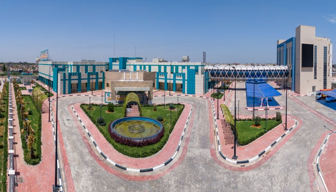
بالصور: ستفتتحه العتبة الحسينية الاسبوع المقبل.. شاهد ما يحتويه مستشفى الثقلين لعلاج الاورام في البصرة من اجهزة طبية
|
|
|
|
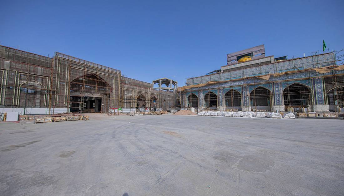
صممت على الطراز المعماري الإسلامي وتضم (16) قبة.. تعرف على نسب الإنجاز بقاعة علي الأكبر (ع) ضمن مشروع صحن عقيلة زينب (ع)
|
|
|
|
عبر جناحين.. العتبة الحسينية تشارك في معرض طهران الدولي للكتاب
|
|
|
|
بالفيديو: بحضور الامين العام للعتبة الحسينية وبالتعاون مع جامعتي واسط والقادسية.. قسم الشؤون الفكرية والثقافية يقيم المؤتمر العلمي الدولي الثالث تحت عنوان (القرآن الكريم والعربية آفاق و إعجاز)
|